Pulse Echo Method in Ultrasonic Testing
views:4,420
author:admin
source:Hiwave
time:2025-03-13
catogory:Industry News
What is pulse echo method in ultrasonic testing?
The pulse-echo method is a commonly utilized technique in ultras……
What is pulse echo method in ultrasonic testing?
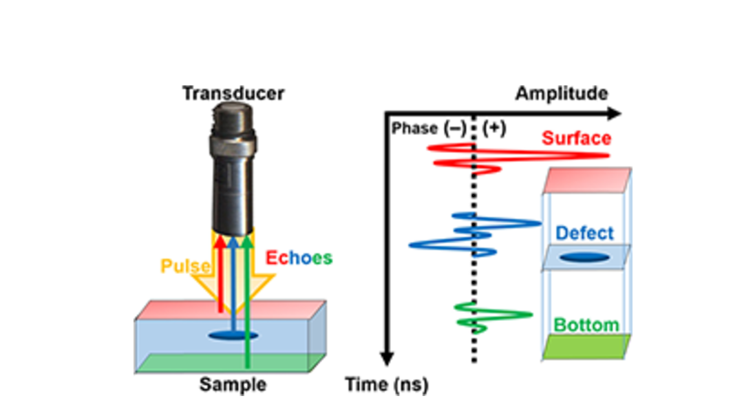
The pulse-echo method is a commonly utilized technique in ultrasonic testing to detect defects inside materials, including cracks, pores, voids, welding deficiencies, and others. The fundamental principle is based on transmitting ultrasonic wave pulses and subsequently receiving the echoed signals. Analysis of these signals’ time differences and intensities allows for assessing the size and position of the defects.
Steps Involved in the Pulse-Echo Ultrasonic Testing Method.
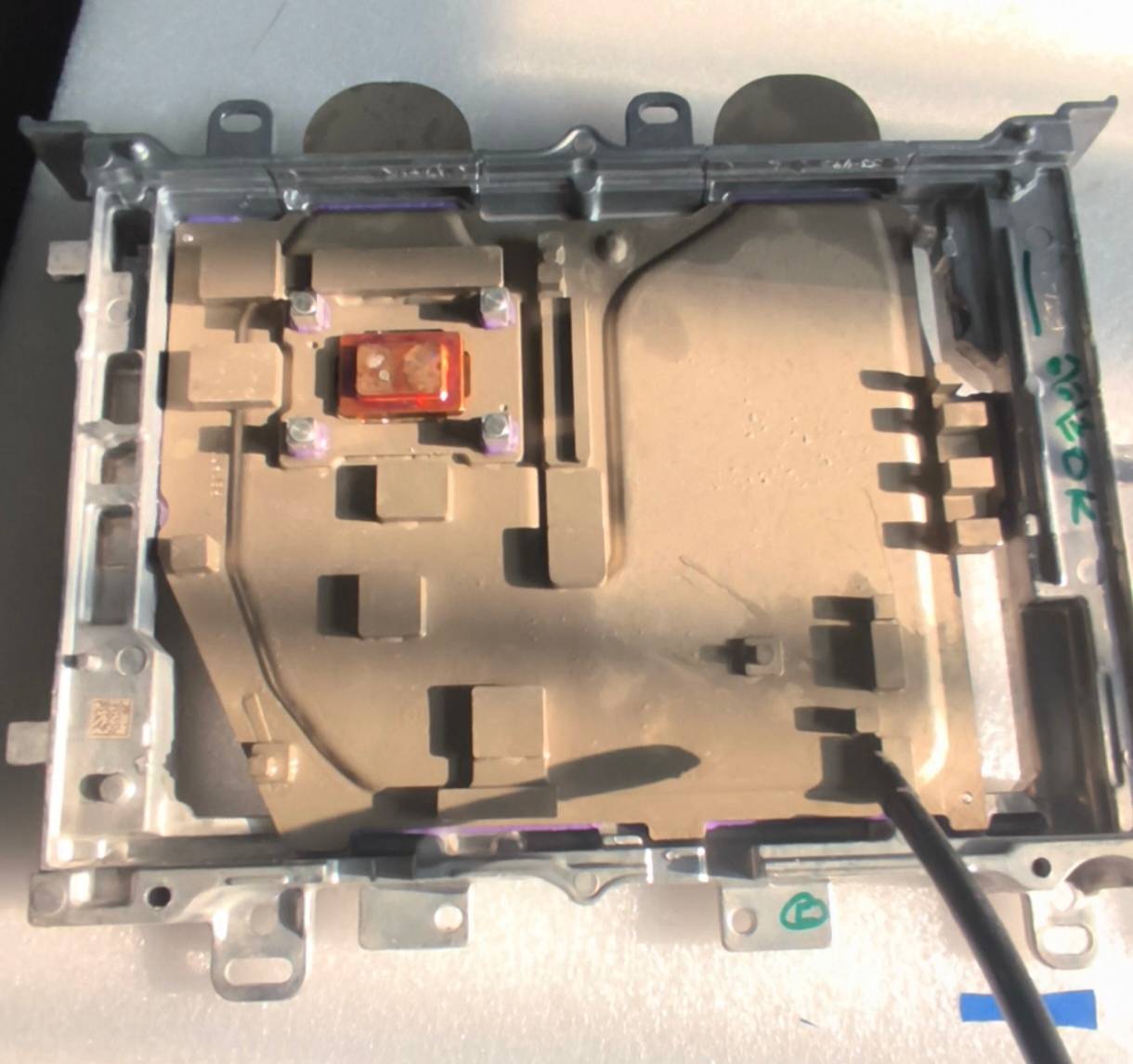
Example of Using the Pulse-Echo Method to Inspect a Heat Sink
Step 1: Sample Preparation
Clean the welding surface of the water-cooled plate to remove oxidation layers, oil stains, or burrs, ensuring good contact with the probe. Secure the water-cooled plate to a fixture to prevent movement during heat sink scanning. Fill the water tank with water as a coupling agent.
Step 2: Equipment Calibration
Select a standard block that matches the material of the water-cooled plate (e.g., copper, aluminum, stainless steel) and calibrate the sound velocity accordingly.
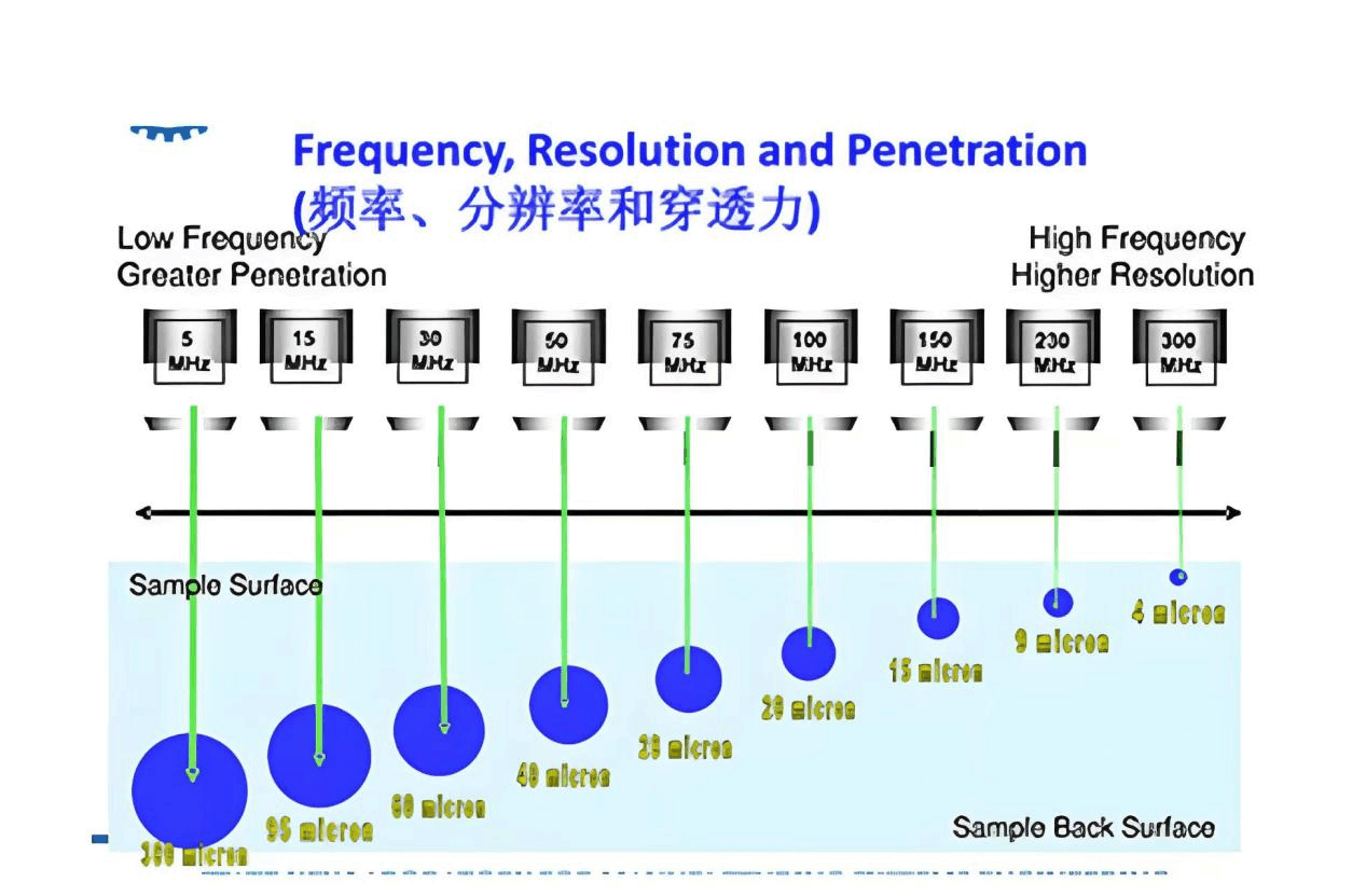
Step 3: Probe Selection For inspecting water-cooled plates, a probe frequency of 50 MHz with a focal length of 2 mm is typically used.
Tip: The probe frequency is directly proportional to the detection accuracy; higher frequencies result in higher precision images. Conversely, the probe frequency is inversely proportional to the thickness of the sample that can be inspected; higher frequencies allow for inspection of thinner samples.
Step 4: Preliminary Scanning Open the A-SCAN interface to quickly scan the weld area, looking for anomalies (e.g., high-amplitude, wide-band signals which may indicate cracks). Adjust the probe position to focus on potential defect areas.
Step 5: Detailed Imaging
Once the defect location is identified, perform detailed scans of the defect area. After multiple scans, determine specific details such as the type, location, and size of the defect. Common defect types in water-cooled plates include lack of fusion, porosity, cracks, and slag inclusion.
Step 6: Visualization Report
Assess the size and severity of the defects according to standards and color-code them accordingly.
Step 7: Data Storage
Save the B-scan and C-scan images along with the A-scan waveform data into the original files.