Analysis of Theoretical and Actual Signals in Scanning Acoustic Microscopy
views:535
author:Hiwave
source:Hiwave
time:2025-07-16
catogory:Frequently Asked Questions
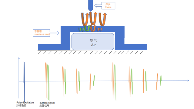
When using a scanning acoustic microscope (SAM) for material inspection, a key issue often arises: there is a significant difference between the theoretical waveform……
When using a scanning acoustic microscope (SAM) for material inspection, a key issue often arises: there is a significant difference between the theoretical waveform and the actual waveform detected. This discrepancy not only affects data accuracy but also poses challenges for defect identification and localization. So, what causes this phenomenon, and how can it be further analyzed?
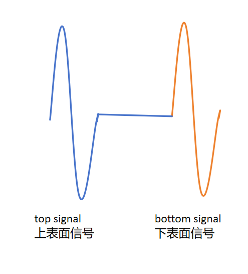
Pulse Excitation Signal: This is the initial signal generated when the transducer emits the ultrasonic wave.
Top Surface Echo: When the ultrasonic wave first reaches the top surface of the sample, part of the energy is reflected back, forming the first distinct wave peak.
Bottom Surface Echo: After passing through the top surface, the ultrasonic wave continues to propagate downward and is reflected again at the bottom surface, forming a second major wave peak.
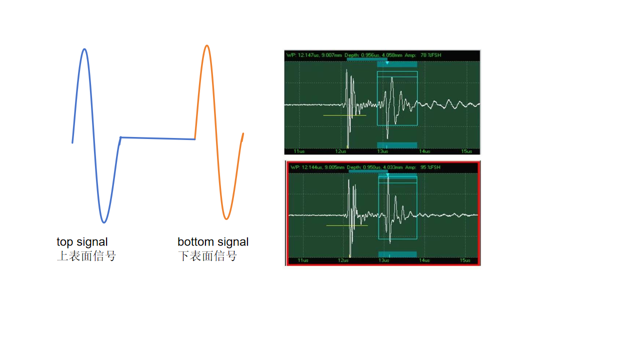
However, in actual testing, the observed waveform is much more complex than this simplified model. Multiple wave peaks are often present, and in some cases, the phenomenon of “multiple wave groups” can be observed.
 According to the basic principles of ultrasonic wave propagation, the expected waveform is as follows: