How to Select a suitable Transducer (Including Calculation)
views:552
author:Hiwave
source:Hiwave
time:2025-08-29
catogory:Frequently Asked Questions
The ultrasonic transducer is the most critical accessory in a Scanning Acoustic Microscope, and focal length is one of the core parameters of the transducer. For ins……
The ultrasonic transducer is the most critical accessory in a Scanning Acoustic Microscope, and focal length is one of the core parameters of the transducer. For instance, transducers of the same frequency (e.g., 25MHz) are often available with various focal length specifications (such as 0.5 inches, 1.0 inch, 1.5 inches, etc.). Faced with different focal length options, how should we select the most suitable one based on actual requirements?
Basic Structure of an Ultrasonic Transducer
Unlike optical microscopes, which achieve focusing using convex lenses, ultrasonic focusing is accomplished through a concave acoustic lens. In front of this concave acoustic lens is mounted a piezoelectric ceramic (piezoelectric element). When an electrical pulse is applied, the piezoelectric element rapidly deforms and generates a vibration, emitting a single wave that propagates forward as a plane wave. As the sound wave passes through the front acoustic lens, its wavefront is refracted and gradually converges, ultimately forming a high-energy focal point at the focus.
Transducer Focal Length Calculation
Next, we will focus on how to calculate and select the appropriate transducer focal length.
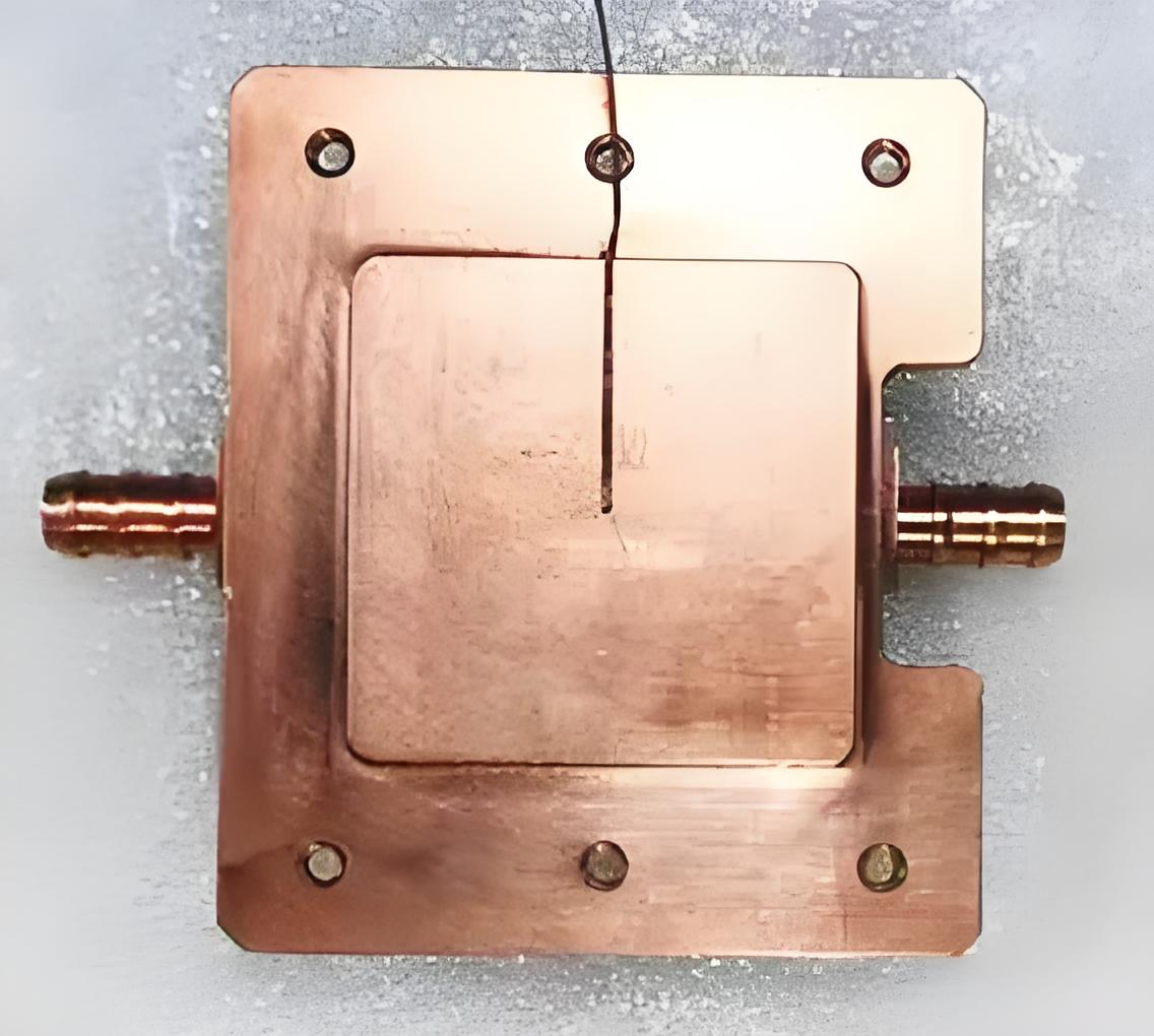
Let’s use the following sample for illustration: The sample is made of red copper, with a welded joint on the upper layer. The thickness from the surface to the welded joint is 2 mm. Based on inspection requirements, we have already determined that a 25 MHz transducer should be used. However, multiple 25 MHz transducers with different focal lengths are available on the market, such as 25 MHz – 0.5 in, 25 MHz – 0.75 in, 25 MHz – 1.0 in, and 25 MHz – 1.5 in. Using this practical sample as an example, we will now perform detailed calculations and analysis to determine how to select the most suitable focal length.
In actual inspection, our goal is to select an appropriate focal length such that when the product is placed beneath the transducer, the weld interface to be inspected is precisely positioned at the focal point of the acoustic beam. This ensures optimal resolution and signal strength.
To achieve more accurate positioning, we can divide the total focal length into two parts:
Upper Segment: Known as the Water Path, this is the distance the sound wave travels through the water coupling medium.
Lower Segment: This corresponds to the thickness of the product. Since the speed of sound in the product differs from that in water, this thickness effectively offsets a portion of the transducer’s focal length. This part is called the Equivalent Focal Length (Fi).
The formula for calculating the equivalent focal length is: Fi = (Speed of Sound in Product / Speed of Sound in Water) * Thickness of Product
For irregularly shaped products with protruding structures (e.g., a raised feature on the top surface), we also need to conclude the Top Height (L_top), which is the height of the highest point of the products relative to the reference plane.
During scanning, the vertical distance between the transducer and the product must be controlled within a reasonable range, typically divided into three zones:
Dangerous Zone: The transducer position is below the safe height, posing a collision risk.
Optimal Zone: The transducer is located between the safe height and the optimal height. Within this zone, not only is the risk of collision low, but the water path is also shorter, resulting in less acoustic energy attenuation and higher resolution. This is the ideal scanning operating range.
Operational Zone: The transducer is above the optimal height. Although inspection is possible, an excessively long water path leads to increased signal attenuation and reduced resolution, making it a non-optimal choice.
Therefore, we can calculate the range for the Comfort Zone:
Optimal Zone Lower Limit (FLmin) = Equivalent Focal Length (Fi) + Top Height (L_top) + Safety Distance (L_safe)
Optimal Zone Upper Limit (FLmax) = FLmin + Optimal Height
Ultimately, the suitable transducer focal length should satisfy: FLmin < Actual Focal Length < FLmax
Calculation with Actual Values
Now, let’s substitute specific values for calculation:
Speed of Sound in Copper Product: 4700 m/s
Speed of Sound in Water: 1500 m/s
Product Thickness: 2 mm
Top Height (L_top): 5 mm
Safety Distance (L_safe): 10 mm
Comfort Height: 10 mm
Calculations:
Equivalent Focal Length Fi = (4700 / 1500) × 2 ≈ 6.27 mm
FLmin = 6.27 + 5 + 10 = 21.27 mm
FLmax = 21.27 + 10 = 31.27 mm
Therefore, the recommended transducer focal length range is 21.27 mm to 31.27 mm (approximately 0.84 in to 1.23 in). Selecting a 25 MHz transducer with a focal length within this range (e.g., 1.0 in) ensures that the weld interface will be positioned within the optimal focal region, enabling efficient and high-resolution inspection.


