Semiconductor Failure Analysis Machine
views:428
author:Hiwave
source:Hiwave
time:2025-09-12
catogory:Industry News
The reliability of integrated circuit (IC) packaging largely depends on its mechanical integrity. Structural defects such as poor adhesion, voids, micro-cracks, or d……
The reliability of integrated circuit (IC) packaging largely depends on its mechanical integrity. Structural defects such as poor adhesion, voids, micro-cracks, or delamination may not be immediately visible in electrical performance but can significantly reduce device lifespan and cause premature failure.
C-Mode Scanning Acoustic Microscopy (C-SAM) is a powerful non-destructive failure analysis tool for IC packaging. It offers high sensitivity in detecting interface anomalies such as poor bonding and delamination, as well as voids, cracks, and foreign material inclusions. By using non-destructive ultrasonic testing, C-SAM provides a reliable and accurate method for detecting delamination or crack defects in semiconductors, making it a widely adopted solution for quality assurance and reliability testing.
Scanning Modes of C-Mode Scanning Acoustic Microscopy (C-SAM)
Three scanning modes are commonly used to display pulse-echo information. In A-scan mode, the transducer does not perform an x–y scan, and only a one-dimensional signal at a specific point is obtained without generating an image. In B-scan mode, the transducer scans along a line to produce a two-dimensional image, where one axis represents the transducer’s x-position and the other axis represents the time of flight of the reflected pulse. The amplitude of the reflected pulse is mapped as intensity along the time-of-flight axis, resulting in a cross-sectional view of the sample. In C-scan mode, the transducer moves in a raster pattern to generate a two-dimensional image, in which the x–y positions of the image correspond to the transducer’s x–y positions. The image intensity at a given x–y position is proportional to the amplitude of the reflected signal at a selected time of flight. By applying this time gate, a C-mode image can be generated to visualize defects at a specific depth within the sample.
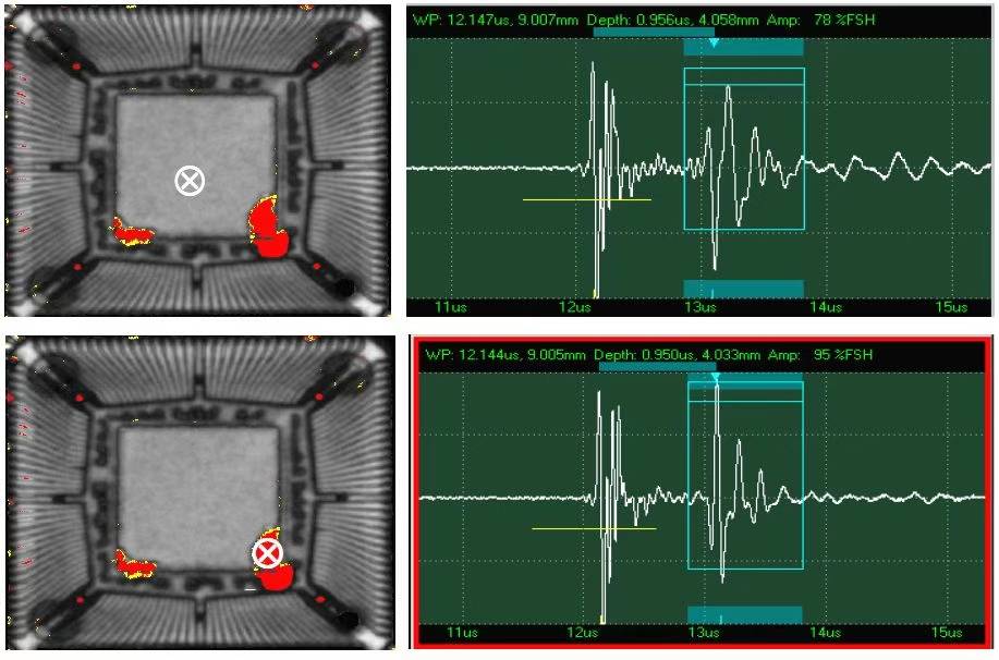
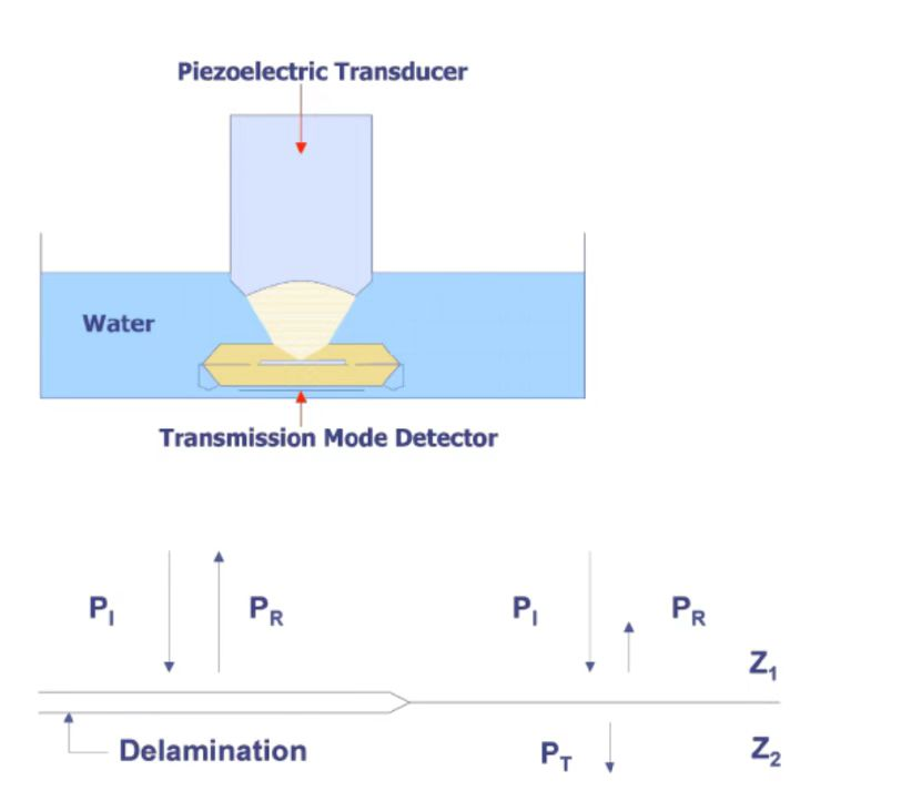
In summary, C-Mode Scanning Acoustic Microscopy (C-SAM) operates by transmitting very short acoustic pulses through a transducer and receiving the reflected echoes from both external and internal interfaces of the sample. By correlating the echo return time with the depth of each interface, internal structural imaging can be achieved.
As illustrated, interfaces at different depths generate signals with distinct time delays—for example, the initial surface echo may appear at approximately 0.5 microseconds, while an internal delamination echo may be delayed to about 1 microsecond—thus clearly revealing internal defects or delamination within the sample.